


Pavako RC Engineering

© 2015 P. van Kooten
TELEMETRY
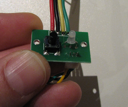
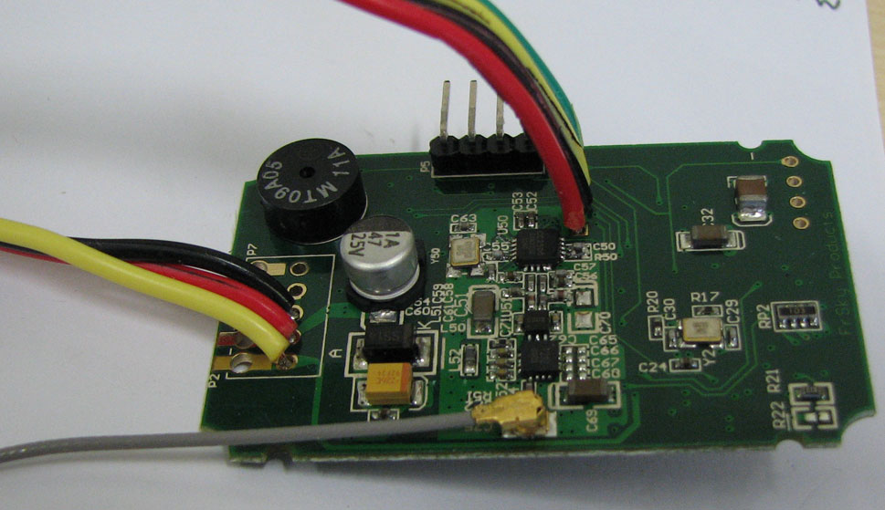
To avoid the mounting of different PCB modules in my Futaba transmitter I decided to integrate the FrSky module on a so-called main PCB. This PCB should contain the FrSky Telemetry module, all required connections for Bind / Range check switch (located on the control panel PCB), the mode switch to enable FW upgrade, 1-WAY or 2-WAY communication. It should contain also the main connection to the Futaba main PCB with the required signals PPM, V+ and GND. Last but not least an interface to the two color LED, to indicate the status of the FrSky module.Other features of this main PCB are : Low drop regulator (+3V3) to supply the RS-232 / TTL levelshifter to intererface to a µcontroller that we do need to decode and display the telemetry information. The main PCB should be located on the exact position were the original connection was for the 35 MHz RF module. The pictures below show the internal electronics of the FrSky module after taking the heat shrink of the module.


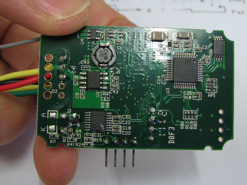
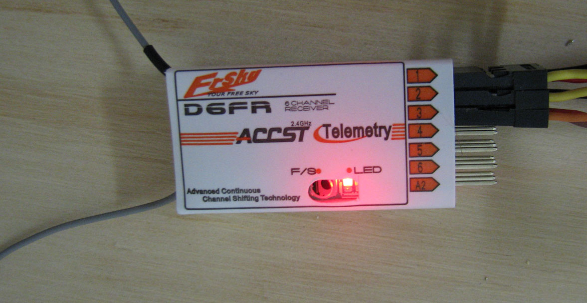
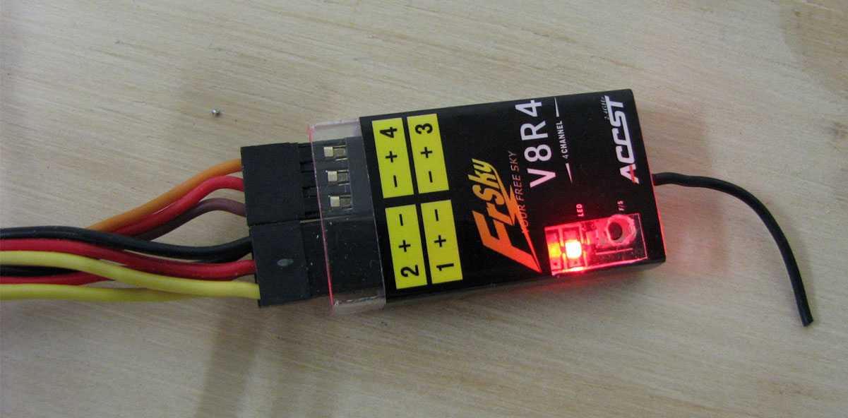
After I removed the heat shrink of the module i did a quick test to verify i didn't damage anything.
I took for this test the 1-WAY and 2-WAY receiver to make sure everything is alright.
I took for this test the 1-WAY and 2-WAY receiver to make sure everything is alright.