


Pavako RC Engineering

© 2015 P. van Kooten
TELEMETRY


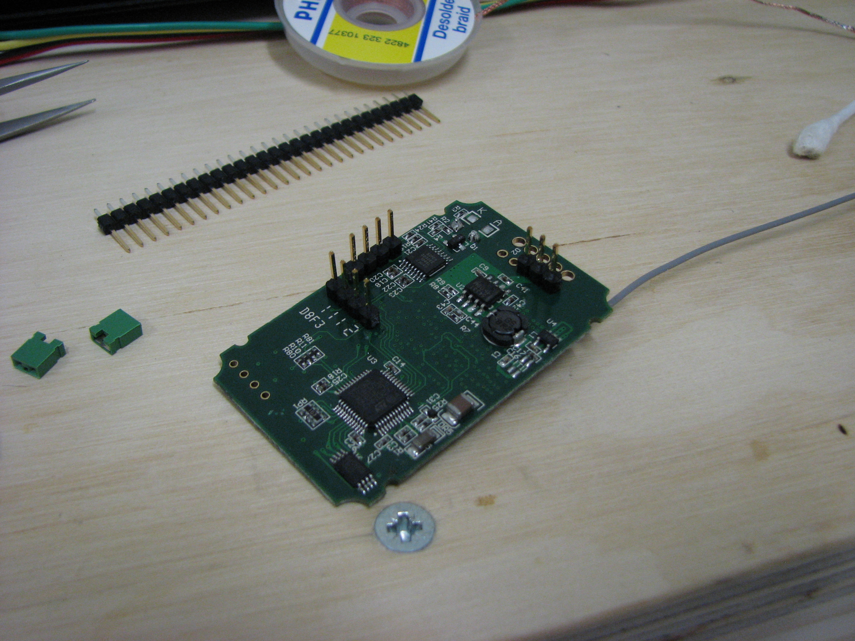
After testing the FrSky module I removed the wires and replaced them by pin headers. (2.54mm pitch)
This will be later the interface towards the main PCB. The first version and the electric diagram can be found here : Schematic MainBoard.
This will be later the interface towards the main PCB. The first version and the electric diagram can be found here : Schematic MainBoard.

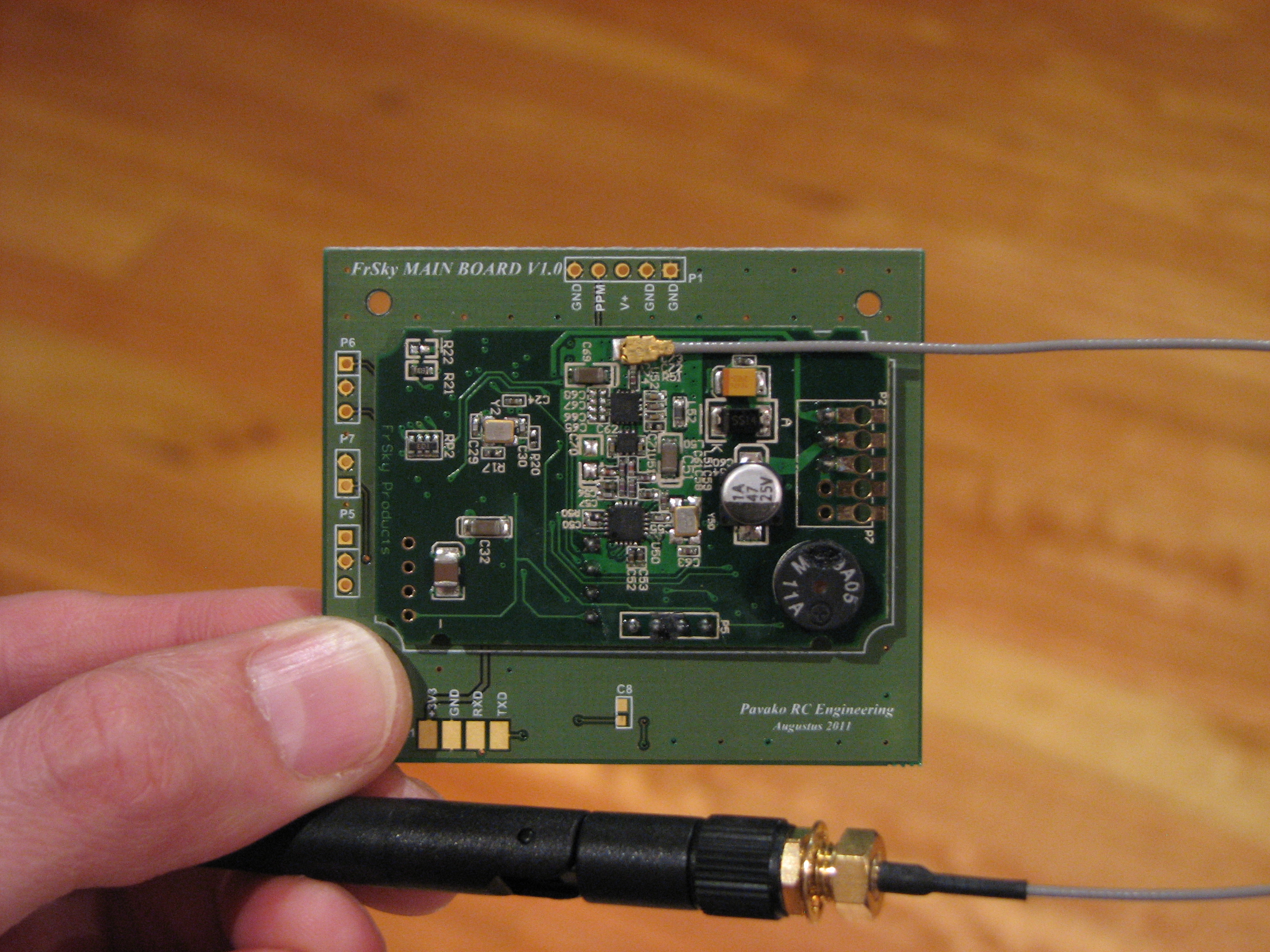
PPM, V+ and GND
connection
connection

TxD, RxD, +5V and GND

CONTROL PANEL
connection
connection
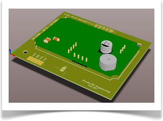
This first version will be used to test the FrSky module and it will the base for doing the first Telemetry tests. A representation of the assembly is shown as well. The first prototype of the main PCB is shown in the picture below. Together with the FrSky module mounted it can be fitted inside my FC-18 transmitter.