


Pavako RC Engineering

© 2015 P. van Kooten
TELEMETRY


PPM, V+ and GND
connection
connection

TxD, RxD, +5V and GND

CONTROL PANEL
connection
connection
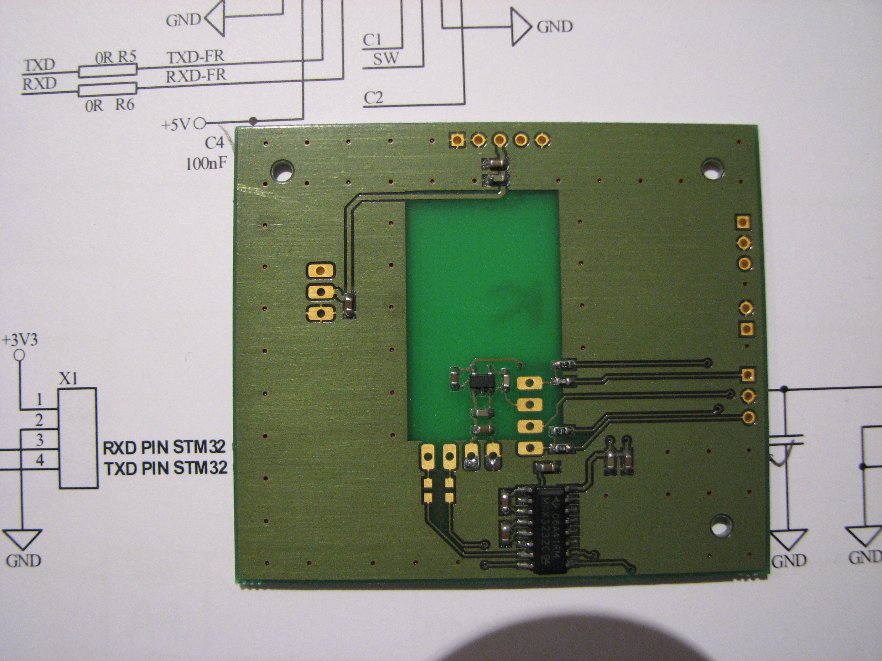
For the assembly of the parts on the BOTTOM side of the PCB I had to look into the original PCB file, cause I forgot to add the BOTTOM overlay :(. Anyway for these few components not a real big deal, and besides that it is version 1.0 :). Before adding the FrSky module I first tested the LDO (Low drop regulator) that delivers the +3V3 voltage for the RS232 levelshifter and a future µcontroller. the final assembly, with FrSky module is shown in the right picture.
LDO

RS232 levelshifter


All connections inside the transmitter will be made using the pin headers. Further steps to install the mainboard are described below. For detailed information please refer to the pictures.
Installation of the mainboard:
STEP 1
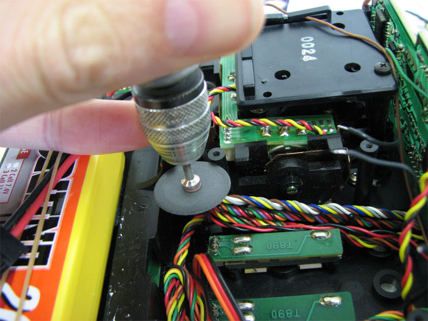
Reduce height of plastic stand-off inside the transmitter. I am not sure what the original function of this stand-off was, but it was actually longer than the other plastic stand-offs. A bit annoying when the mainboard is not properly fitted, because of this...L
Reduce height of plastic stand-off inside the transmitter. I am not sure what the original function of this stand-off was, but it was actually longer than the other plastic stand-offs. A bit annoying when the mainboard is not properly fitted, because of this...L